| Karma, The Blimp |
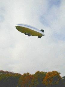
We acquired and AS-500 model from the english company Airspeed
Airships. Criteria for this choice were the size of the blimp (which
we wanted to be rather small, for the ease of deployment and stocking),
its available payload and its possible operation modes.
Nominal specifications According to the constructor, the technical characteristics of the original AS-500 model are the following:
- 7.8 m long, 1.80 m max diameter, giving a volume of about 15.0 m³, and a fitness ratio of 4.25.
- Vectorized thrust (100° range), with two 7.5 cm³ engines, allowing speeds up to 45 km/h, possible control in wind gusts up to 25 km/h, and an endurance of 40 minutes with a 1.0 kg fuel load.
- The hull is made of welded mylar, and equipped with 4 control rudders in a ``X shape'' configuration. A ballonet fed with air captured at the rear of the propellers maintains a constant hull pressure, and a radio-controlled valve on top of the hull can release helium when the temperature is getting higher.
- The static payload of the AS-500 ( i.e to reach the equilibrium) is 3.5 kg, and the blimp must always be overweighted of 1.5 to 2.0 kg in flight: the maximal available payload is therefore about 5 kg.
Specific modifications In collaboration with Airspeed Airships, we specified the following modifications for our purpose:
- Electric motors: to have a finer controllability, we preferred to opt for electric motors. They do not weigh more than fuel engines, but are less powerful, thus reducing the maximum reachable speed and the possibility to fly in wind gusts. Their main drawback is the weight of the required batteries, which considerably reduces the available payload. However, thanks to lighter batteries and possible alternative energy sources, this drawback can be overcomed.
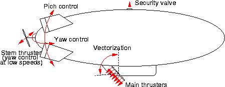
- Stern thruster: the rudder control surfaces require a certain speed to allow changes in both the altitude and orientation of the blimp. In order to have the possibility to maneuver the blimp while hovering, we choose to add a stern thruster, that gives the possibility to control the yaw angle.

The various controls available on the blimp
On-board equipment
To transform the blimp from a radio-controlled machine to a robot, we are currently equipping it with a set of proprioceptive and exteroceptive sensors, and with computing and communications capabilities.
- Stereovision One of the advantage of having a big platform is that it can carry a wide base stereo bench, thus having the possibility to directly gather 3D data on the overflown ground. We adapted 2 high resolution digital B&W cameras on a rigid 2 m carbon profile that traverses the 1.4 m long AS-500 gondola (use of stereo imagery to build a high resolution DEM is presented here).
- Blimp state observation In order to tackle the flight control problem (and also to ease the development of mapping algorithms), we added the following sensors: a differential GPS receiver, a fluxgate compass, that also provide the blimp pitch and roll angles, and a wind sensor (sonar transducer technology), that measures the speed and orientation of the relative wind in the longitudinal plane.
- CPU We opted for a Matrox 4Sight board: it is an EBX form factor PC motherboard, endowed with all the necessary communication ports (100base-T ethernet, two USB ports, two RS232 ports, 16 TTLs, and especially 3 firewire ports). The board comprises a PC104 slot, on which we added four more RS232 ports and a PCMCIA interface to host a light 11 Mbits/s ethernet modem card. Thanks to the 566 Mhz Celeron processor, vision algorithms will eventually run on-board the CPU.
- Actuator control The control surfaces and motor servos of the blimp are usual PWM controlled modelist devices. We use a single chip (a FerretTronics FT629) that can generate up to 8 sustained PWM signals from a RS232 input to control the actuators. For safety reasons, it is essential that an operator can retrieve the blimp control from the ground with the radio, at anytime: this is done thanks to a radio controlled switch, that cuts the PWM signals coming out from the chip.
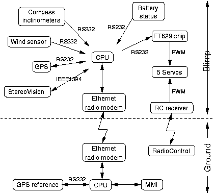
The whole hardware architecture is sketched in the figure below, and some specifications of the various devices are summarized in the following table. The total equipment weight is 1.520 kg, which leaves only 1.300 kg for the various mechanical parts, wires and batteries that must provide the necessary additional 40 W.

Schematic view of the on-board equipment
| Device | Brand/model | Weight (g) | Power requirements (x Watts @ y Volts) |
Comments |
|---|---|---|---|---|
| Compass / Inclinometer | Precision Nav. / TCM2 | 30 g | 0.25 W @ 12 V | yaw : 1.0° RMS; Pitch/Roll : 0.2° RMS |
| Wind sensor | LCJ Capteurs / CV3F | 240 g | 0.6 W @ 12 V | Acc.: 0.05 m/s, 1.5° |
| GPS | Trimble / Lassen SK II | 110 g | 2.0 W @ 5 V | Acc.: 2 m CEP, 0.05 m/s |
| Stereo Cameras | Vitana/PL-A633 | 2 x 80 g | 2 x 3 W @ 12 V | 1280 x 1024 B&W images, 10 bits pixels |
| Lenses | Cosmicar / 12mm F 1.2 | 2 x 65 g | 36° x 45° field of view | |
| CPU | Matrox/4Sight | 850 g | 30 W @ 12 V | Including 2 PC104 boards, 20 Go HD, modem |
| Total | 1.520 kg | < 40 W @ 12 V |
Characteristics of the on-board equipment
Energy management
Energy is a critical issue for any flying device, mainly for safety
considerations. In our case, we also would like to have more autonomy,
while satisfying the maximal payload constraint.
Our AS-500 was originally equipped with 3 sets of NiCd batteries: one
for the radio receiver and the servos (4.8 V, 1.2 Ah,
0.140 kg), one for the stern thruster (7.2 V, 2.0 Ah,
0.350 kg) and one for the main thrusters (14.4 v, 5.0 Ah,
1.880 kg).
We decided to replace the two thruster batteries with Lithium/Ion
batteries, that have a much more interesting power/weight ratio (about
2.5 times better, which respectively saves 1.200 kg and 0.200 kg
weight for the main and stern thrusters), and to feed the instruments
with an other separate set of batteries. In total, the blimp now has 4
power sources, each of them being critical for its operation. So each
battery is managed by a Maxim MAX1648 chip, that allows both the
``intelligent'' charge of the battery and the dispatching of status
informations to the CPU via a multiplexed serial link. The four charging
modules are linked to a single connector, on which a power source is
plugged while the blimp is on the ground (which allows booting and
debugging without any power loss), and on which a rescue set of non
rechargeable Lithium/Ion batteries is plugged in flight (an additional
weight of only 0.200 kg to deliver 5.0 Ah @ 15 V). This very
flexible structure also allows the future use of an alternate power
source on flight, such as a Stirling engine of a fuel cell.
Current status
At the date of Feb the 15th 2002, the whole equipment mechanical integration is under way. All the on-board added equipment (besides the stereo bench and the wind sensor, which is mounted on the nose of the blimp) fits into a drawer-like box that can be easily removed from the gondola. The following additional devices are considered:
More sensors
The various blimp state estimation sensors mentioned above provide the sufficient informations to tackle flight control in aerostatic mode (i.e. hovering or flying at very low speeds). But to control aerodynamic modes, the pitch and yaw rate informations are necessary. We do not know whether the derivation of these informations from the inclinometers will be suitable or not: if not, we will add two solid-state rate gyros for that purpose. Also, the altitude estimate provided by the GPS receiver is not precise enough to safely servo the taking-off and landing phases: for that purpose, we will add a sonar telemeter. Fortunately, the main drawback of sonars in robotics, i.e. their wide perception cone which make their data interpretation so tedious, will turn into an advantage in our case, as there will be no need to mechanically stabilize it along the vertical. Finally, we are still investigating for a 3D wind sensor (Pitot tubes are unfortunately not sensitive enough at the low blimp speeds).
Energy issues
As mentioned above, energy is a critical issue for a blimp. In our case, the square/cube law deters the use of solar cells (an airship surface grows up with the square of its dimension, whereas its volume grows up with the cube. This has important consequences on airship controllability in wind gusts, the aerodynamic forces and the inertia being respectively proportional to the square and the cube, but also on the possibility to use solar cells). A very appealing solution would be to use a Stirling engine, that could provide a large autonomy: we are currently investigating to find an engine that would deliver a few tens of Watts. Our choice of energy management can easily benefit from such a device, which output would simply be plugged to the main connector. The batteries will be kept, to ensure the possibility to deliver high energy when required (during taking-off for instance).
| People Involved |
Sara Fleury, Matthieu Herrb, Simon Lacroix, Xavier "steelfingers" Dollat, Patrick "goldfingers" Marcoul, Arnaud Jacquet.
|
Robots
|
Rovers Navigation
|
Autonomous Blimps
|
Multi-Robot Cooperation
|
